 SUPPORT



 3EX United States
Blog
A higher uptime tier doesn’t eliminate downtime; it changes how much redundancy a facility has to withstand failures and maintenance. Tier I is the baseline: it uses a single distribution path and has no redundant capacity, with a specified uptime of 99.671% per year. Understanding data center facility redundancy standards starts with this distinction between basic capacity and backup systems.
It’s reasonable to expect a higher tier to mean stronger protection, but the label alone doesn’t explain how power, cooling, or maintenance affect service continuity. This guide explains what Tier I means, how Uptime Institute tiers differ, and how facility design and ongoing maintenance shape redundancy and downtime protection. You’ll see what N+1 and 2N mean in practice, why separate systems matter, and how to assess the level of resilience that fits your infrastructure needs.
Key Takeaways
- Tier I provides a single power and cooling distribution path with no redundancy, so identify how much interruption your workloads can tolerate.
- Compare tiers by their redundancy and maintenance design, not just their uptime figures; Tier III supports concurrent maintenance, while Tier IV is designed to tolerate a single unplanned failure.
- Assess power, cooling, and network paths separately, then use regular load testing and maintenance to verify that backup systems can perform when needed.
- Match the facility arrangement to your infrastructure needs: full cabinets, private suites, and cage solutions offer different ways to house server hardware.
What is a Tier I data center?
A Tier I facility has one distribution path and enough power and cooling capacity for its full IT load, but no redundancy. This tier classification helps clarify what may happen when equipment fails or requires maintenance.
Tier I Power and Cooling Infrastructure
Tier I power and cooling infrastructure relies on a single path to deliver essential services to IT equipment. It has capacity for the full load, but no backup path if that route is disrupted. A fault or planned work along the path can therefore interrupt service. Reliability depends on the path’s condition and how the facility responds to failures.
Redundant Power and Cooling Components
Redundant components provide backup capacity, but they do not automatically create independent distribution paths. A power supply or power distribution unit (PDU) may have a spare, while a shared switch remains a single point of failure. Dual-corded servers can connect to separate sources only if the complete power paths are independent. Tier I design does not provide this redundancy by default. Cooling paths also require separate assessment.
Redundancy Configurations and Standards
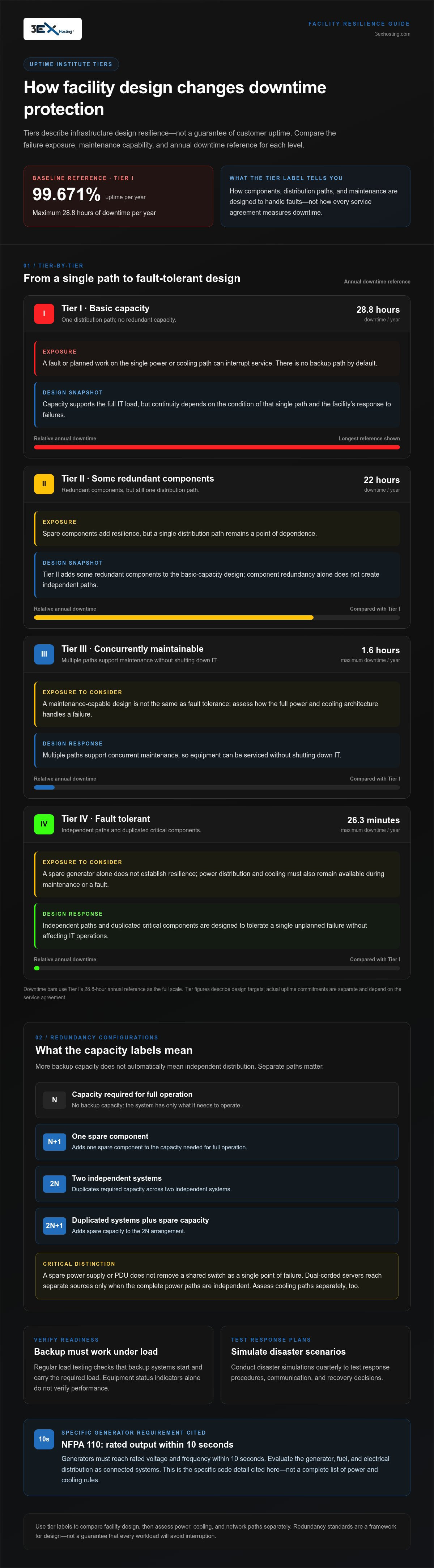
N is the capacity needed for full operation, with no backup; N+1 adds one spare component. 2N duplicates the required capacity in two independent systems, while 2N+1 adds spare capacity to that arrangement. ANSI/TIA-942 is associated with tier-classification methodology and describes topology, cabling, redundancy levels, and physical layout. The material on ASHRAE does not establish a universal N+1 or 2N requirement. NFPA 110 states that generators must reach rated voltage and frequency within 10 seconds. Evaluate generator, fuel, and electrical distribution paths as connected systems. Tier I specifies 99.671% uptime per year; Tier II specifies 99.741% yearly, with some redundant components but a single distribution path. In the United States, the cited generator requirement is the specific code detail relevant here, not a complete list of power and cooling rules.
Redundancy Costs
N+1 adds spare components; 2N duplicates systems and paths, increasing equipment and infrastructure needs. Construction and operating costs depend on capacity, equipment, and maintenance requirements, so there is no single cost increase that applies to every facility. As a practical reference, review data center infrastructure alongside your redundancy needs.
Uptime Institute tier classifications
The Uptime Institute classification system groups facilities into four tiers, from basic capacity to fault-tolerant design. These data center facility redundancy standards describe infrastructure design, not a guarantee of customer uptime.
Tier Levels and Availability
The Uptime Institute tier classification describes design resilience through components, distribution paths, and maintenance capabilities. Tier I provides basic capacity; Tier II adds some redundant components but retains a single distribution path. Tier III supports concurrent maintenance through multiple paths, while Tier IV is fault tolerant, with independent paths and duplicated critical components.
These differences link facility design to availability. A spare generator, for example, can improve resilience, but power distribution and cooling must also remain available during maintenance or a fault. Assess the full infrastructure rather than treating one component as proof of a tier. Data center facility redundancy standards provide a framework for comparing these dependencies.
Expected Uptime and Downtime
Expected uptime and annual downtime translate each tier’s design classification into a reference level of service availability. Redundancy standards describe facility design; an uptime guarantee is a separate commitment set out in a service agreement. Data center facility redundancy standards alone do not describe every disruption or explain how a specific workload will be affected.
- Tier I: 99.671% uptime per year; maximum 28.8 hours of downtime per year.
- Tier II: 99.741% uptime yearly; 22 hours of downtime yearly.
- Tier III: 99.982% uptime per year; no more than 1.6 hours of downtime per year.
- Tier IV: 99.995% uptime per year; no more than 26.3 minutes of downtime per year.
Use these values to compare design targets, then examine what the service agreement counts as downtime. Planned maintenance, measurement periods, and covered systems affect how an uptime commitment applies. For a practical infrastructure comparison, explore data center infrastructure alongside your availability requirements.
Facility design and ongoing maintenance
Resilient facility design combines backup capacity with maintenance that keeps equipment ready. For mission-critical operations, availability depends on preparing for both planned work and unexpected failures.
Maintenance and Failure Resilience
Resilience to maintenance and failures requires infrastructure and operating routines that keep essential systems available during faults and service work. A backup system helps only if it starts and carries the required load. Operators use regular load testing to verify readiness and performance instead of relying solely on equipment status indicators.
Disaster planning adds another layer. Conduct disaster simulations quarterly to test response procedures, communication, and recovery decisions. A generator fire at a data center in Ogden, Utah, shut the facility down for an extended period in 2021, showing how a failure in backup infrastructure can affect service.
Concurrent Maintainability and Fault Tolerance
Concurrent maintainability allows equipment to be serviced without shutting down IT. Fault tolerance is designed to withstand a failure without affecting IT operations. These are distinct resilience goals, and each depends on the facility’s complete power and cooling architecture.
Tier III design uses N+1 redundancy and multiple power and cooling distribution paths to support concurrent maintenance. Tier IV uses multiple independent paths and is designed to tolerate a single unplanned failure. For operators, the difference is whether maintenance or a component failure can interrupt the primary service path.
Generator and fuel maintenance should test the complete backup sequence, from fuel availability to generator operation and electrical delivery. Load testing checks performance under operating conditions, while inspections can reveal issues a visual status check may miss. Record fuel-system checks, generator test results, and corrective work so recurring faults can inform the next maintenance cycle.
A useful disaster exercise follows a realistic scenario from detection through escalation and recovery. Involve the people responsible for facilities and IT, then record where decisions or handoffs slowed the response. This connects the written plan to actual operations and helps teams refine procedures before a disruption affects mission-critical workloads.
Data center redundancy and downtime protection
Redundancy protects workloads only when backup capacity remains usable across the complete service path. Power, cooling, and network connections can all affect downtime, so assess a facility’s rating against your workloads’ failure tolerance. A resilient power design cannot protect equipment if cooling stops or network connectivity is lost. Consider every dependency that must remain available for a service to keep operating.
Outage figures show why separate systems matter. Between 2019 and 2022, 80% of data centers experienced outages, and 60% of outages cost more than $100,000. UPS failures were linked to 43% of data center outages. These figures don’t show that one design prevents every outage. They highlight the need to examine backup systems, shared dependencies, and how components behave under failure conditions.
Trace each critical workload through its power and cooling path. Check where utility feeds, UPS systems, generators, transfer equipment, and rack connections share components. A backup source offers limited protection if a common switch or distribution path can interrupt both sources. Static transfer systems switch between power sources in a few milliseconds, but they are useful only when independent sources are available.
Capacity matters during a failure. Backup systems must support the critical load while the remaining infrastructure continues to deliver power and cooling. Evaluate network connectivity separately rather than assuming one redundancy rating covers every subsystem. Then compare the design’s failure tolerance with the interruptions your applications can withstand. This makes the rating more useful than treating it as a standalone uptime promise.
When assessing facility infrastructure, include data center infrastructure as part of a broader continuity review. Consider how the physical environment aligns with your power, cooling, and recovery requirements.
3EX Hosting: Full Cabinet Colocation
3EX Hosting provides Full Cabinet Colocation for organizations that need secure, dedicated space for server hardware. It’s a practical option when your team manages its own equipment and wants it housed in a data center environment. For a different footprint, Private Colocation Suites and Cage Solutions datacenter offer alternative physical-space arrangements.
Choose an arrangement that suits your hardware, space requirements, and operating model. If you’re moving some infrastructure away from equipment your team manages directly, Managed Cloud Hosting may be a better fit. These options serve different needs: colocation provides physical space for your servers, while managed cloud hosting supports a cloud-based approach.
Contact 3EX Hosting to discuss your infrastructure needs, or visit 3exhosting.com.
Make resilience part of your next infrastructure decision
Use your continuity objectives to guide the next infrastructure decision. Map which workloads can tolerate interruption, which systems must remain available during maintenance, and where shared dependencies could undermine your design. Then match the facility arrangement to how your team manages equipment and operations. The right choice should meet your requirements without adding complexity that does not improve resilience.
For organizations evaluating colocation, 3EX Hosting offers Full Cabinet Colocation, Private Colocation Suites, and Cage Solutions datacenter. Consider these options in light of your equipment footprint and operational model. A clear understanding of data center facility redundancy standards can help frame that discussion, but the facility’s actual power, cooling, and maintenance design should guide your evaluation.
Take the next step by discussing your infrastructure needs with 3EX Hosting. Contact 3EX Hosting to explore a suitable path forward. A deliberate assessment now can help your team make a more informed decision and move ahead with confidence.
Frequently Asked Questions
What Are Uptime Tier Standards?
Uptime tier standards classify data center design resilience, rather than guaranteeing a customer’s service availability. They provide a common way to describe infrastructure design, maintenance needs, and tolerance for failures. For an evaluation, compare the facility’s stated tier with its actual power, cooling, and distribution architecture. Then review the service agreement separately, since contractual uptime commitments are distinct from a design classification.
What are the Uptime Institute Tier standards for data center redundancy?
The Uptime Institute defines four tiers, with design expectations ranging from basic capacity to fault-tolerant infrastructure. Tier I and Tier II retain a single distribution path, although Tier II includes some redundant components. Tier III supports concurrent maintenance through multiple paths. Tier IV uses independent paths and is designed to tolerate a single unplanned failure. Check whether the classification covers the systems your workloads depend on.
What redundancy levels are required for data center power systems and UPS capacity?
No single redundancy level applies to every data center power system; capacity and design depend on the critical load and required resilience. A useful review traces power from its sources through the UPS and distribution equipment to server connections. Include recovery conditions: battery charging after a deep discharge can add load of up to 20% of the UPS rating. This affects how backup capacity performs after an outage.
What cooling redundancy configurations are used in data centers, and how are they rated?
Cooling can use spare components or independent distribution paths, and its resilience should be evaluated separately from electrical redundancy. Tier III designs use N+1 redundancy and multiple power and cooling distribution paths to support concurrent maintenance. Tier IV provides fully redundant, independently active cooling and power distribution paths. A facility’s overall tier describes its design classification; it doesn’t mean every cooling component has the same configuration.
What are common risks and failure modes in redundant data center infrastructure?
Common risks include shared components that defeat supposedly separate paths, UPS failure, generator problems, and loss of cooling. A practical review follows a failure scenario through the entire system: identify the affected component, trace what remains operational, and assess whether backup equipment can carry the load. Regular load testing helps verify readiness, while disaster simulations reveal gaps in response procedures and recovery coordination.