 SUPPORT


 3EX United States
 Blog
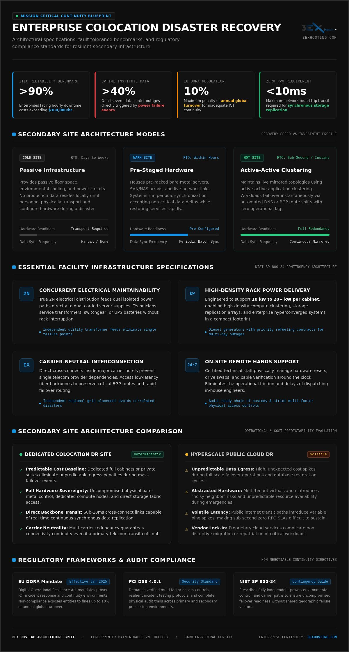
According to ITIC reliability benchmarks, over 90 percent of enterprises face downtime costs exceeding $300,000 per hour. Yet treating secondary infrastructure as merely idle backup space is where most continuity strategies collapse. Deploying an enterprise-grade colocation disaster recovery site requires far more than reserving cold floor space. It demands carrier-neutral network density, reliable power scaling, and continuous operational readiness from day one.
You already know that hyperscale cloud disaster recovery models introduce unpredictable egress fees and volatile latency during live failovers. At the same time, managing distant physical hardware during an active incident can stretch internal engineering teams past their limits. You need absolute hardware-level control and multi-carrier redundancy, but you can’t afford the operational friction of dispatching staff for routine maintenance or sudden hardware resets.
This guide shows you how to architect, evaluate, and deploy a resilient colocation disaster recovery site that secures enterprise continuity, meets strict RPO and RTO targets, and keeps your operating costs predictable. We’ll examine the critical infrastructure specifications, high-density power topologies, and network capabilities needed to protect your mission-critical workloads in 2026.
Key Takeaways
- Architecting an enterprise colocation disaster recovery site requires concurrently maintainable power topologies and carrier-neutral cross-connects rather than passive, unmonitored floor space.
- Deploying dedicated full cabinets or private suites protects operational budgets from unpredictable public cloud data egress penalties during mass failover events.
- Strategic site selection demands placing secondary infrastructure on an independent regional power grid outside your primary facility’s hazard radius to prevent correlated outages.
- Leveraging 24/7 on-site remote hands support guarantees rapid physical troubleshooting and scheduled maintenance without dispatching internal engineering staff.
- Rigorous, non-disruptive failover testing validates strict recovery time and zero-data-loss recovery point objectives against modern compliance mandates.
Colocation Disaster Recovery: What It Is & Why It Matters
A colocation disaster recovery site functions as an independent, secondary facility engineered to host redundant production hardware. Rather than treating this location as simple real estate, enterprise continuity plans treat it as an active defense mechanism. Power outages account for over 40 percent of severe data center failures according to Uptime Institute research. Secondary deployments isolate your critical applications from localized power grid collapses, catastrophic hardware destruction, and upstream transit cuts.
Rigorous regulatory frameworks leave no room for operational ambiguity. Compliance standards like the EU Digital Operational Resilience Act (DORA), effective January 2025, impose severe fines up to 10 percent of annual global turnover for inadequate ICT continuity. Similarly, PCI DSS 4.0.1 mandates proven multi-factor controls and resilient incident response environments. Deploying within enterprise-grade colocation data center infrastructure delivers the physical access controls, environmental monitoring, and audit-ready chain of custody needed to satisfy external examiners.
Cold, Warm, and Hot DR Colocation Sites Explained
Secondary sites operate across three primary technical models:
- Cold Sites: Provide passive floor space, environmental cooling, and power circuits. No production data resides locally until engineering teams physically transport and configure hardware during a disaster. Recovery takes days or weeks.
- Warm Sites: House pre-racked bare-metal servers, SAN/NAS arrays, and live network links. Systems run periodic data synchronization, accepting non-critical data deltas while restoring services within hours.
- Hot Sites: Maintain live mirrored topologies using active-active application clustering. Workloads fail over instantaneously via automated DNS or BGP route shifts with zero operational lag.
Defining RPO and RTO Targets for Secondary Facilities
Recovery Point Objective (RPO) defines the maximum allowable data loss measured in elapsed time. Recovery Time Objective (RTO) dictates how many minutes or hours business operations can tolerate an outage before financial degradation becomes catastrophic.
Your hardware deployment topology dictates whether sub-second metrics are achievable. Achieving zero RPO demands synchronous storage replication, requiring sub-10-millisecond round-trip network transit. A purpose-built colocation disaster recovery site provides direct cross-connect access to ultra-low-latency fiber backbones, enabling continuous data pipelines that prevent transaction loss during unannounced primary failures.
Essential Infrastructure Specifications for a Disaster Recovery Facility
Fault-tolerant engineering forms the backbone of true business continuity. An enterprise colocation disaster recovery site must remain operational when surrounding municipal utilities fail. In line with the NIST SP 800-34 contingency planning guidelines, secondary sites require fully independent power, environmental control, and carrier paths to ensure uncompromised failover readiness. If primary systems drop, your secondary site must absorb production workloads without a hitch.
Power Distribution and Concurrent Maintainability
Eliminating single points of failure starts at the utility transformer. True 2N electrical distribution provides two fully independent, isolated power paths directly to dual-corded server supplies. Concurrently maintainable topologies allow technicians to service transformers, switchgear, or UPS batteries without taking downstream racks offline. On-site diesel generators with priority refueling contracts safeguard extended operations through multi-day regional blackouts. Modern deployments also demand high-density power delivery of 10 kW to 20+ kW per cabinet, letting you run dense compute clusters in a compact physical footprint.
Carrier-Neutral Interconnection and Cross-Connects
Carrier neutrality guarantees your secondary site never depends on a single upstream telecom provider. Facilities positioned within major carrier hotels offer direct physical cross-connects to diverse Tier 1 backbones, regional transit providers, and cloud on-ramps. Physical diversity requires:
- Dual, geographically separated fiber entry vaults entering opposite sides of the building.
- Isolated Meet-Me Rooms (MMRs) to prevent localized physical damage from disconnecting all external transit.
- Diverse intra-facility pathways terminating directly into your secure cabinets or suites.
These redundant paths preserve low-latency synchronization and guarantee traffic can instantly reroute over alternate carriers if an upstream fiber cut occurs.
Environmental Control and Advanced Fire Suppression
High-density hardware generates intense thermal loads that overwhelm conventional cooling. Precision hot/cold aisle containment systems maintain stable intake temperatures, preventing thermal throttling during peak failover execution. Clean agent gaseous suppression systems extinguish fire hazards instantly without water, leaving sensitive electronic circuits and solid-state storage undamaged. Early warning aspirating smoke detection continuously samples air particles, alerting facility engineers to thermal anomalies well before combustion occurs.
Pairing fault-tolerant infrastructure with dedicated cabinet colocation guarantees that your physical secondary environment delivers the control, power capacity, and network reach your continuity roadmap demands.
Colocation DR Site vs. Public Cloud Disaster Recovery
Public cloud Disaster Recovery as a Service (DRaaS) appeals to teams seeking zero initial hardware investment. However, treating cloud platforms as a default backup environment introduces hidden financial and architectural traps. When an entire production footprint fails over, network saturation and variable consumption models often derail recovery objectives. Incorporating the Ready.gov IT disaster recovery planning framework into your evaluation highlights the practical trade-offs between virtualized multi-tenant platforms and deterministic colocation facilities.
Cost Predictability and Egress Expense Analysis
Budget volatility remains the primary drawback of hyperscale public cloud recovery. Cloud vendors generally charge between $0.08 and $0.09 per gigabyte for outbound data transfer. While providers introduced conditional exit-waivers following European Data Act regulations, ongoing cross-region synchronization and sudden mass repatriation remain fully billable. Replicating hundreds of terabytes under emergency conditions triggers punitive egress penalties and API call fees.
A dedicated colocation disaster recovery site replaces unpredictable consumption models with fixed, transparent operational commitments. Bandwidth costs stay flat via predictable cross-connects and unmetered dark fiber links. Over three- to five-year lifecycles, hosting stable, high-throughput database workloads on dedicated bare-metal infrastructure yields substantially lower total cost of ownership compared to holding idle cloud VM capacity.
Compliance, Data Sovereignty, and Hardware Control
Public cloud architectures restrict operational autonomy. Hypervisor configurations, storage controllers, and kernel-level settings remain entirely under the provider’s command. During major hyperscaler regional outages, thousands of tenants concurrently demand elastic compute, frequently triggering capacity provisioning errors precisely when systems need to scale.
Deploying inside dedicated private data center suites guarantees exclusive physical custody and complete architectural discretion. Consider these enterprise advantages:
- No Resource Contention: Dedicated chassis and SAN switches prevent noisy-neighbor performance bottlenecks during intense I/O rebuilds.
- Hardware Sovereignty: Custom cryptographic modules, bare-metal database engines, and legacy storage arrays run without translation layers.
- Regulatory Isolation: Physical access logs, dedicated biometric entry gates, and isolated perimeter cages satisfy external compliance audits effortlessly.
Many enterprises ultimately adopt a hybrid disaster recovery posture. High-churn relational databases and compliance-restricted workloads stay pinned to a secure colocation disaster recovery site, while stateless, transient web frontends leverage public cloud auto-scaling during peak emergencies.
Strategic Framework for Selecting a National Colocation DR Facility
Selecting an off-site recovery destination requires rigorous separation analysis. Positioning your backup environment too close to your headquarters creates correlated vulnerabilities where a single hurricane, flood, or grid blackout disables both locations at once. Conversely, pushing equipment thousands of miles away introduces network latency that strains active replication streams. Engineering a resilient colocation disaster recovery site demands balancing physical detachment against operational responsiveness.
Geographic Distance and Low-Latency Balance
Fiber propagation adds roughly one millisecond of latency per 100 miles of physical fiber transit each way, translating to approximately two milliseconds of round-trip time (RTT). Keeping your secondary footprint within 60 miles enables synchronous replication with sub-five-millisecond RTT, which is vital for transactional database engines that cannot tolerate write delays. Facilities placed beyond 100 miles demand asynchronous replication schedules to avoid application bottlenecks.
True geographic resilience also requires separate utility footprints. Ensure your secondary facility operates on an independent regional grid system, like separating workloads between the Eastern, Western, or Texas interconnects. That deliberate partition guarantees a widespread regional grid collapse cannot take down your entire enterprise topology simultaneously.
The Role of 24/7 Remote Hands Support
Downtime incidents rarely occur during convenient working hours. When disk arrays fail, fiber jumpers snap, or hardware freezes during scheduled failover simulations, sending internal engineers across the country on commercial flights burns valuable recovery hours. Professional on-site technicians act as an immediate physical extension of your network operations center.
Leveraging on-demand remote hands support ensures that qualified personnel handle physical component swaps, complex patch-panel rerouting, and visual diagnostic checks 24/7/365. This round-the-clock coverage guarantees prompt physical execution without requiring local engineering staffing.
Security, Compliance, and Audit Readiness
Physical boundaries must match the defense-in-depth protocols applied across your logical network layer. Validated SOC 2 Type II, ISO/IEC 27001, and HIPAA compliance alignments prove a facility maintains rigorous physical safeguards. Multi-factor biometric scanners, monitored mantrap portals, and uninterrupted video recording prevent unauthorized physical tampering.
Deploying inside customizable cage solutions datacenter environments creates isolated, steel-mesh perimeters tailored specifically for enterprise hardware footprints. These private perimeters segregate sensitive storage racks from shared multi-tenant pathways, establishing clear audit trails that satisfy external security inspectors.
Ready to deploy a high-resilience secondary environment? Get a custom quote to size your dedicated power, rack footprint, and cross-connect requirements today.
Deploying and Testing Your Colocation Disaster Recovery Architecture
A continuity architecture remains merely theoretical until validated under controlled stress. Human error and procedural oversights account for 66 to 80 percent of all downtime events according to Uptime Institute analysis. Executing an orderly deployment pipeline transforms passive floor space into an active, dependable recovery environment. Follow this systematic rollout framework:
- Phase 1: Footprint Provisioning: Calculate power requirements and reserve dedicated cabinet colocation or private suite space configured with concurrently maintainable A/B power feeds.
- Phase 2: Network Carrier Interconnection: Establish diverse cross-connects inside carrier-neutral Meet-Me Rooms to provision unmetered replication links to your primary facility.
- Phase 3: Hardware Staging: Rack bare-metal hypervisors, mount SAN storage, and establish isolated management pathways.
- Phase 4: Replication Configuration: Map storage volumes, initiate baseline disk mirroring, and configure automated snapshot schedules.
- Phase 5: Failover Validation: Execute structured network isolation tests to benchmark recovery execution against predefined continuity objectives.
Hardware Deployment and Out-of-Band Network Access
Prevent configuration drift by mirroring production server profiles identically at your secondary site. When equipment arrives, technical teams must establish dedicated, air-gapped out-of-band (OOB) management links using independent LTE cellular modems or secondary ISP circuits. This terminal-server layer lets system administrators access IPMI, iDRAC, and console switches even if your primary production routes crash. Structured overhead cabling and documented rack elevations guarantee off-site technicians can locate and trace physical ports instantly.
Executing Non-Disruptive Failover Simulations
Paper-based tabletop reviews don’t reveal how networking stacks behave during sudden disruptions. Modern disaster recovery validation relies on hypervisor network fencing and isolated VLAN overlays. This structure enables full-stack recovery drills during business hours without corrupting live production databases or disrupting customer traffic.
Measure failover duration continuously. If enterprise services take four hours to restore against a two-hour RTO metric, analyze hypervisor boot sequencing, BGP route advertising speeds, and DNS time-to-live settings to eliminate bottlenecks. Maintain detailed runbooks that define specific command escalations, vendor support contacts, and on-site physical handoff protocols. An engineered colocation disaster recovery site gives your operational team the control and validation tooling required to guarantee seamless recovery when an actual disaster strikes.
Future-Proof Your Business Continuity with Resilient Infrastructure
Enterprise resilience can’t rely on unvalidated assumptions or unpredictable cloud bills. True operational readiness requires a dedicated colocation disaster recovery site engineered for continuous uptime. By securing full cabinet or private suite allocations backed by high-density power delivery, your organization gains deterministic control over hardware environments while eliminating surprise egress fees. Operating within a carrier-neutral carrier hotel provides the diverse, low-latency cross-connects necessary to maintain real-time replication pipelines without data loss.
Physical execution is just as critical as raw network capacity. Having access to 24/7/365 on-site technical remote hands support guarantees routine maintenance, drive replacements, and emergency diagnostics happen immediately, keeping your strict recovery targets intact without dispatching traveling engineers. Protect your mission-critical applications and establish predictable continuity. Request an enterprise colocation consultation to design a fault-tolerant disaster recovery architecture tailored to your compliance and performance mandates.
Frequently Asked Questions
How far away should a colocation disaster recovery site be located?
Your secondary site should sit outside your primary facility’s immediate hazard footprint while respecting application latency budgets. A separation of 50 to 100 miles protects against localized power blackouts while enabling low-latency synchronous database replication under five milliseconds round-trip. For broad regional hazards like grid collapse or hurricanes, place the secondary facility hundreds of miles away on an independent electrical interconnect using asynchronous replication.
What is the practical difference between a warm site and a hot site in colocation?
A hot site operates active-active infrastructure with live data mirroring, enabling automated failover in seconds. A warm site houses pre-configured servers, storage arrays, and network feeds, but ingests scheduled data updates rather than live transactions. Restoring operations from a warm site takes minutes or hours, making it an economical option for workloads that don’t mandate zero data loss.
Why are carrier-neutral cross-connects essential for a disaster recovery data center?
Carrier-neutral cross-connects eliminate single-vendor transit risk. By housing your colocation disaster recovery site inside a carrier hotel with multi-provider access, your infrastructure connects directly to multiple Tier 1 backbones via physically diverse Meet-Me Rooms. If a commercial carrier suffers a backhoe cut or BGP routing failure, traffic automatically routes over alternate upstream fiber paths without dropping your replication links.
How does 24/7 remote hands support assist during an active disaster recovery event?
On-site remote hands technicians act as your local engineering team during an emergency. They reseat dropped fiber lines, swap failed hard drives, power-cycle frozen hypervisors, and patch physical cables on demand. This round-the-clock coverage eliminates the multi-hour delays of dispatching internal system administrators to a distant physical data center during critical recovery windows.
Can our business use a colocation disaster recovery site for active test environments?
Yes, enterprises routinely run staging workloads, QA environments, and non-disruptive failover simulations on secondary hardware. Using hypervisor network isolation and private VLAN segmentation, engineers test disaster recovery runbooks against mirrored datasets without exposing production systems to risk. This practice validates recovery procedures while deriving continuous operational value from secondary hardware investments.
How do we calculate power density requirements for an enterprise secondary site?
Calculate power requirements by summing nameplate draw across all intended production servers, SAN arrays, and core switches, then derating to roughly 80 percent of circuit capacity to meet electrical standards. High-density virtualization and modern compute architectures routinely require 10 kW to 20+ kW per cabinet. Choose a facility capable of scaling power delivery to avoid splitting clusters across unnecessary floor space.
What network failover protocols are typically used between primary and secondary colocation sites?
Enterprises primarily use Border Gateway Protocol (BGP) with autonomous system numbers (ASNs) to dynamically withdraw routes from the failed primary data center and announce them from the secondary site. At the application layer, latency-based and health-checked DNS steering reroutes client requests. For internal database replication, software-defined SD-WAN overlays and dedicated Layer 2 cross-connect extensions maintain direct synchronization paths.