 SUPPORT


 3EX United States
 Blog
What if the redundancy your provider promised is actually a single point of failure disguised by engineering jargon? You already understand that even a brief power interruption can lead to catastrophic financial loss, especially as AI workloads push rack densities toward 200 kW. It’s difficult to justify infrastructure costs to stakeholders when the line between marketing claims and actual engineering standards remains blurred. Mastering the technical details of data center power redundancy (N+1, 2N) isn’t just a technical requirement; it’s a dynamic insurance policy for your mission-critical assets.
This guide provides a professional framework to help you master the technical and strategic differences between N+1, 2N, and 2N+1 architectures. We’ll demystify the Tier standards and the latest NEC 2026 updates so you can audit provider claims with confidence and select the redundancy level your enterprise workload truly requires. By the end of this article, you’ll have a clear ROI-based understanding of how to align your colocation strategy with your specific RTO and RPO objectives to ensure your infrastructure never sees a second of downtime.
Key Takeaways
- Identify why “N” capacity represents a critical single point of failure that leaves your mission-critical infrastructure vulnerable to any component malfunction.
- Compare the technical differences between parallel N+1 protection and fully independent 2N system architectures to eliminate distribution-level risks.
- Audit your infrastructure using a strategic framework that maps data center power redundancy (N+1, 2N) levels directly to your enterprise Recovery Time Objectives.
- Understand why high-density AI and GPU hosting workloads require 2N power standards to maintain stability as rack densities exceed 20kW.
- Learn how to operationalize your redundancy strategy through managed disaster recovery solutions and expert remote hands support.
Understanding “N”: The Baseline of Data Center Power Capacity
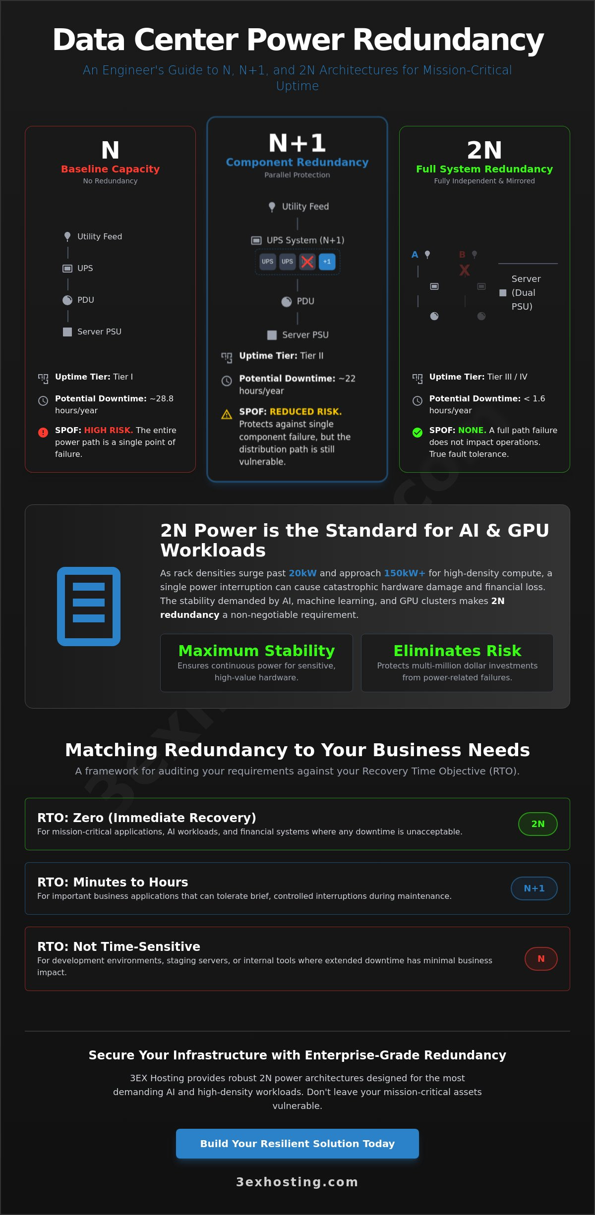
In the world of critical infrastructure, “N” is the variable representing the exact amount of power required to keep your hardware running at full capacity. It’s the baseline. Without N, your systems go dark. While this sounds straightforward, relying on an N-only architecture means you’re operating without a safety net. Every component in the chain becomes a potential catalyst for a total system crash. This configuration aligns with the basic requirements of Tier I Data center tiers, which offer 99.671% uptime. To a casual observer, that sounds high. To an enterprise professional in 2026, it translates to 28.8 hours of potential downtime annually. Evaluating your data center power redundancy (N+1, 2N) strategy begins with this fundamental baseline.
The financial stakes have never been higher. With the cost of building AI data centers reaching $17 million per megawatt, the investment in the hardware itself is massive. An outage doesn’t just halt operations; it risks damaging high-density components and results in significant recovery costs. Industry data from 2025 shows that while outages are declining, 20% of reported failures are classified as significant, often leading to catastrophic financial loss. For modern enterprises, N is no longer a standard for reliability; it’s a vulnerability waiting to be exploited by a single equipment failure.
The Components of the Power Chain
A standard power path is a sequence of critical junctions. It starts at the utility feed, moves through the Uninterruptible Power Supply (UPS), reaches the Power Distribution Unit (PDU), and finally enters the server’s Power Supply Unit (PSU). In an N system, these components are linked in a series. If the UPS fails or a single PDU trips, the entire downstream load loses power immediately. There’s no alternate path for the electricity to travel. Even if a facility has on-site generators, they serve as the ultimate “N” backup but still feed into the same single distribution path. This creates a Single Point of Failure (SPOF) at every single junction of the electrical architecture.
Calculating Your Specific “N” Requirement
Determining your N requirement starts with a precise audit of your current hardware. For a full cabinet colocation setup, you must calculate the nameplate draw versus actual consumption. You shouldn’t just look at the server specs. You need to account for “ghost loads,” which include the power consumed by cooling fans, network switches, and management controllers that often go overlooked in basic estimates. As AI workloads increase rack densities to 60kW or 150kW, accurate calculations are vital for stability. You must also account for future scaling. An N calculation that works today will be insufficient six months from now as you add high-density hardware to your environment. N represents the absolute minimum requirement for operational survival.
N+1 and N+2 Redundancy: The Parallel Protection Model
N+1 redundancy introduces a critical safety margin by adding a single extra module to the base requirement. If your facility needs four UPS modules to handle the load (N=4), an N+1 design provides five. This configuration is often associated with Tier II facilities within the Uptime Institute’s Tier Classification System. It offers a layer of protection that the basic N architecture lacks. It ensures that the failure of a single hardware component doesn’t lead to immediate system-wide failure. Evaluating your data center power redundancy (N+1, 2N) options requires understanding these module-level protections.
This approach is known as “Parallel Redundancy” because the extra unit is integrated into the active system. All units typically share the load during normal operations. If one fails, the remaining units pick up the slack instantly. It’s a cost-effective way to improve reliability without doubling the entire infrastructure. However, it’s vital to remember that N+1 focuses on components, not the entire power path. You’re protecting against a module failure, but you’re not yet protected against a distribution failure.
How N+1 Works During Component Failure
When a UPS module fails in an N+1 environment, the parallel logic shifts the electrical load to the remaining healthy modules. This happens in milliseconds. While this protects against module hardware failure, the limitation is significant. The distribution path remains a single point of failure. If a main breaker trips or a cable fails downstream, the extra UPS module can’t help. Maintenance also becomes a calculated risk. While you can take one unit offline for service, the system reverts to an “N” state during that window. Any secondary failure during maintenance results in a total outage. For complex repairs, utilizing remote hands support can minimize the time your system spends in this vulnerable state.
When N+2 is the Smarter Investment
N+2 redundancy is gaining traction as a standard for enterprise sites that cannot tolerate any “N” state windows. It adds two extra modules beyond the base requirement. This architecture protects against the “failure during maintenance” scenario. If one module is offline for a scheduled battery replacement and another module unexpectedly fails, the system still has its “N” capacity intact. N+2 is particularly valuable for aging facilities or environments with high-wear cycles. The capital expenditure is higher than N+1, but the risk reduction is exponential. It provides a buffer for human error and hardware fatigue. This makes it a logical choice for workloads where even a few minutes of downtime would exceed the cost of the additional hardware.
2N and 2N+1: Achieving Fully Independent System Redundancy
While N+1 redundancy protects individual components, the 2N architecture elevates protection to the entire system level. This configuration, often referred to as “System + System” redundancy, involves two completely independent power paths. Each path, typically labeled as the A-side and the B-side, is capable of supporting the entire IT load on its own. By mirroring every piece of equipment from the utility entrance to the rack, 2N eliminates the distribution-level single points of failure that plague simpler designs. This architecture is the recognized gold standard for private colocation suites and Tier IV facilities where downtime is not an option. Mastering data center power redundancy (N+1, 2N) requires recognizing that 2N is about path independence, not just extra hardware.
For organizations with the most stringent uptime requirements, 2N+1 represents the absolute pinnacle of power engineering. This design combines the system-level independence of 2N with the component-level parallel redundancy of N+1. In a 2N+1 environment, both the A-side and B-side power systems have their own redundant modules. Even if a system is undergoing maintenance and a component fails on the active side, the infrastructure remains fully protected. It’s the ultimate safeguard against the unpredictable nature of complex electrical systems.
The Anatomy of a 2N Power Path
In a true 2N environment, the redundancy starts at the utility level with dual feeds from different substations whenever possible. From there, the power travels through dual UPS strings and dual PDUs before reaching the server rack. Modern enterprise hardware leverages this through dual-corded power supplies. One power cord connects to the A-side PDU while the second connects to the B-side. If the A-side loses power, the server’s internal power supply unit (PSU) automatically draws full current from the B-side without a millisecond of interruption. Fault tolerance ensures the system continues operating during a failure, while fault isolation prevents a failure in one system from affecting the other.
Concurrent Maintainability: The 2N Advantage
The most significant operational benefit of 2N is concurrent maintainability. Engineering teams can shut down an entire power path for major upgrades or repairs without ever touching the live load. This is vital for long-term stability. It eliminates the “maintenance window” anxiety that defines N+1 environments. This architecture also serves as a critical buffer against human error during complex switching procedures. If a technician accidentally trips a breaker on the A-side, the B-side continues to carry the workload. During periods of regional grid instability, having two fully independent paths provides the physical layer of security needed to maintain 100% availability for mission-critical assets.
Choosing Your Redundancy Level: A Strategic Framework
Selecting the right architecture requires a shift from viewing power as a utility to treating it as a risk management strategy. Your Recovery Time Objective (RTO) is the primary driver. If your business can tolerate the time it takes to switch to a backup generator or replace a single UPS module, N+1 might suffice. However, for mission-critical applications where RTO is near zero, the dual-path nature of 2N is non-negotiable. The decision often hinges on the density of the workload. Traditional setups at 5kW per rack offer more thermal buffer than modern AI clusters. When you exceed 20kW per rack, any power failure becomes an immediate cooling crisis. Evaluating your data center power redundancy (N+1, 2N) needs means balancing these physical realities against your operational goals.
Cloud-native applications often rely on software-level redundancy across multiple regions. While this adds a layer of protection, it shouldn’t replace physical infrastructure stability. The latency and egress costs of moving massive datasets during a local power failure are often prohibitive. Physical hardware redundancy remains the most cost-effective first line of defense. It ensures that your local environment remains stable so your software never has to trigger a complex, multi-region failover event in the first place.
Redundancy for High-Density GPU and AI Hosting
In the context of high density GPU colocation, power and cooling are inseparable. High-density servers generate intense heat; if power to the cooling systems fails even for a minute, thermal runaway can occur. This risks damaging expensive H100 or B200 clusters. This makes 2N redundancy a technical necessity for massive AI training clusters. Even within a cage solutions datacenter environment, you must ensure that the redundancy extends to the rack level. It’s not enough for the facility to have 2N power if your specific cage is limited by a single distribution path.
The ROI of “Over-Engineering” Your Power
The cost of 2N power is often questioned until the first regional grid event occurs. Calculate the insurance value by comparing the incremental cost of 2N against the financial impact of a single four-hour outage. For many enterprises, the loss of revenue and reputation during that window far exceeds the multi-year premium of a redundant power feed. Beyond immediate uptime, compliance frameworks like SOC2, HIPAA, and PCI-DSS often require documented proof of high availability. Choosing a robust data center power redundancy (N+1, 2N) configuration future-proofs your infrastructure for the 2026-2030 hardware cycles, where AI workloads are expected to reach 40% of all data center activity.
When auditing a provider, look past the marketing brochures. Ask to see the physical separation of A and B side switchgear. Verify that the maintenance logs show concurrent maintainability in practice. If you’re ready to secure a facility that meets these engineering standards, request a technical consultation and quote to see how our infrastructure aligns with your specific density requirements.
Operationalizing Redundancy with 3EX Hosting
Implementing a robust data center power redundancy (N+1, 2N) strategy is the difference between operational resilience and catastrophic failure. 3EX Hosting provides enterprise-grade 2N power as a standard for mission-critical environments. We understand that your hardware requires more than just a backup generator. It requires a fully mirrored, independent infrastructure that eliminates every single point of failure in the distribution path. Our systems are designed to support the intense demands of modern AI clusters. We ensure that your high-density GPU hardware remains stable regardless of grid conditions or component wear.
Physical redundancy is only as effective as the team managing it. Our remote hands support serves as an essential human layer of your uptime strategy. Whether it’s a routine swap of a dual-corded PSU or managing a complex failover event, our on-site technicians provide the expertise needed to maintain system integrity. We also offer transparent power monitoring and rigorous SLA guarantees. This provides real-time visibility into your consumption and the peace of mind that your infrastructure is performing to its technical specifications.
Transitioning complex redundant deployments can be a logistical challenge. We simplify this through our move-in assistance program. Our engineers work directly with your team to map out A and B side power distributions before your hardware arrives at the loading dock. This proactive approach ensures that your redundancy is operational from day one. It minimizes the risks associated with migration downtime and ensures your hardware is balanced across independent circuits immediately.
Beyond the UPS: The 3EX Infrastructure Advantage
Our carrier-neutral connectivity complements our power architecture by providing diverse network paths. 3EX infrastructure is built for speed and reliability, featuring 24/7/365 on-site technical expertise to manage critical systems. We can customize power configurations to meet specialized enterprise requirements. This includes specific voltage needs or unique rack densities that exceed standard colocation offerings. We align our facility operations with the latest NEC 2026 standards to ensure your deployment is both safe and compliant.
Get Started with a Redundancy Audit
Don’t leave your uptime to chance. Consulting with our engineers allows you to match your specific workload to the most effective power architecture. We help you audit your current requirements and plan for the 40% growth in AI workloads projected by 2030. This ensures your footprint can scale as power densities increase. Take the next step toward 100% availability today. Request a Custom Quote for Redundant Colocation and secure your enterprise’s technical future.
Securing the Future of Your Enterprise Infrastructure
Redundancy isn’t just about extra hardware; it’s about eliminating every single point of failure within your power path. You’ve seen how N+1 provides component protection while 2N offers the system-level independence required for modern, high-density AI workloads. As rack densities continue to rise toward 2030, the technical gap between basic availability and true fault tolerance will only widen. Choosing the right level of data center power redundancy (N+1, 2N) ensures your operations remain resilient against both equipment failure and human error.
At 3EX Hosting, we provide 2N power redundancy as a standard to protect your mission-critical loads. Our infrastructure combines carrier-neutral connectivity with the expertise of 24/7 remote hands support to maintain 100% uptime. We handle the technical complexities so you can focus on scaling your business with complete peace of mind. Secure Your Mission-Critical Infrastructure with 3EX Hosting and align your technical strategy with the highest industry standards. Your infrastructure is in expert hands.
Frequently Asked Questions
What is the main difference between N+1 and 2N redundancy?
The main difference lies in component versus system level protection. N+1 redundancy adds a single extra module, such as a UPS or generator, to the base requirement to handle a component failure. In contrast, 2N provides two completely independent and mirrored power systems. While N+1 protects against a module malfunction, only 2N architecture eliminates the distribution path as a single point of failure.
Do I need 2N redundancy if my applications are already load-balanced?
Software-level load balancing doesn’t replace physical infrastructure stability. If your local power path fails in an N+1 environment, the hardware hosting your application goes dark regardless of your software configuration. Utilizing 2N data center power redundancy (N+1, 2N) ensures the physical layer remains active so your software-level failovers aren’t triggered by local electrical faults that could have been avoided.
Can an N+1 system be concurrently maintainable?
Standard N+1 systems aren’t truly concurrently maintainable. You can service a single UPS module, but the system reverts to an “N” state during that window. If another component fails while one is being repaired, you’ll experience a total outage. True concurrent maintainability requires a 2N architecture where an entire power path can be de-energized for major upgrades without risking the live load.
How does 2N+1 redundancy differ from standard 2N?
2N+1 adds a layer of parallel protection to a mirrored system. In a standard 2N setup, each of the two independent sides has exactly enough capacity (N) to carry the load. In a 2N+1 configuration, each side includes an extra module (N+1). This ensures that even if one side is offline for maintenance and a component fails on the active side, the system remains fully operational.
Is 2N power redundancy required for GPU and AI server hosting?
2N power is the technical standard for high-density GPU and AI hosting due to extreme thermal risks. These workloads often exceed 20kW per rack, where even a brief power loss leads to immediate thermal runaway. 2N architecture provides the necessary stability to protect expensive hardware clusters from sudden outages and the resulting heat-related damage that can occur in seconds.
What happens if a data center with N+1 redundancy suffers two simultaneous component failures?
A total power outage occurs if an N+1 system suffers two simultaneous component failures. The “+1” module is designed to compensate for only one malfunction at a time. Once that spare is utilized, any subsequent failure in the remaining modules will drop the entire IT load. This specific vulnerability is why many modern enterprises are moving toward 2N or N+2 configurations for their mission-critical assets.
How much more does 2N colocation typically cost compared to N+1?
2N redundancy involves higher costs because it requires doubling the entire electrical infrastructure. You’re effectively paying for two of everything, from UPS strings to switchgear and utility feeds. While the monthly recurring costs are higher than N+1, most enterprises view this as a necessary insurance premium. It’s a strategic investment to avoid the catastrophic financial loss associated with a single significant outage.
What is the role of an Automatic Transfer Switch (ATS) in redundancy levels?
An Automatic Transfer Switch (ATS) allows single-corded hardware to benefit from redundant power sources. It monitors two separate feeds and automatically switches to the backup if the primary fails. While useful for legacy equipment, an ATS introduces its own point of failure. Professional data center power redundancy (N+1, 2N) designs prefer dual-corded servers that connect directly to both the A and B power sides.